
A couple printed widgets
Re: a couple printed widgets
before I started my run today, I thought I needed some ChapStick because my lips were dry but decided to go anyway. about 3 miles into the run, I found this on the side of the road, full up and just what I needed, maybe better than ChapStick. probably just a coincidence.  on the other hand, I think if you are destined to fly, a way will be made for you if you apply the effort and do the research.
RV9A, Superior O-320, WW 200RV prop, Slick mags, CHT 330F, EGT 1300F, B&C, 1400+ hours
Freedom and Democracy are all that really matter.
Ride a bike, unlock the world.
https://www.rvplasticparts.com/
Freedom and Democracy are all that really matter.
Ride a bike, unlock the world.
https://www.rvplasticparts.com/
Re: a couple printed widgets
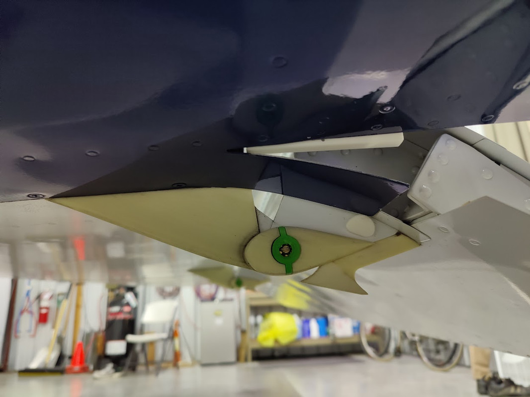
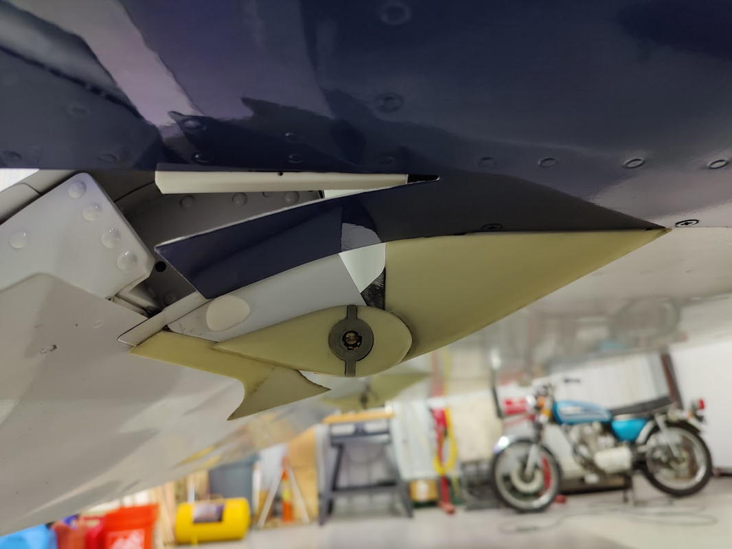
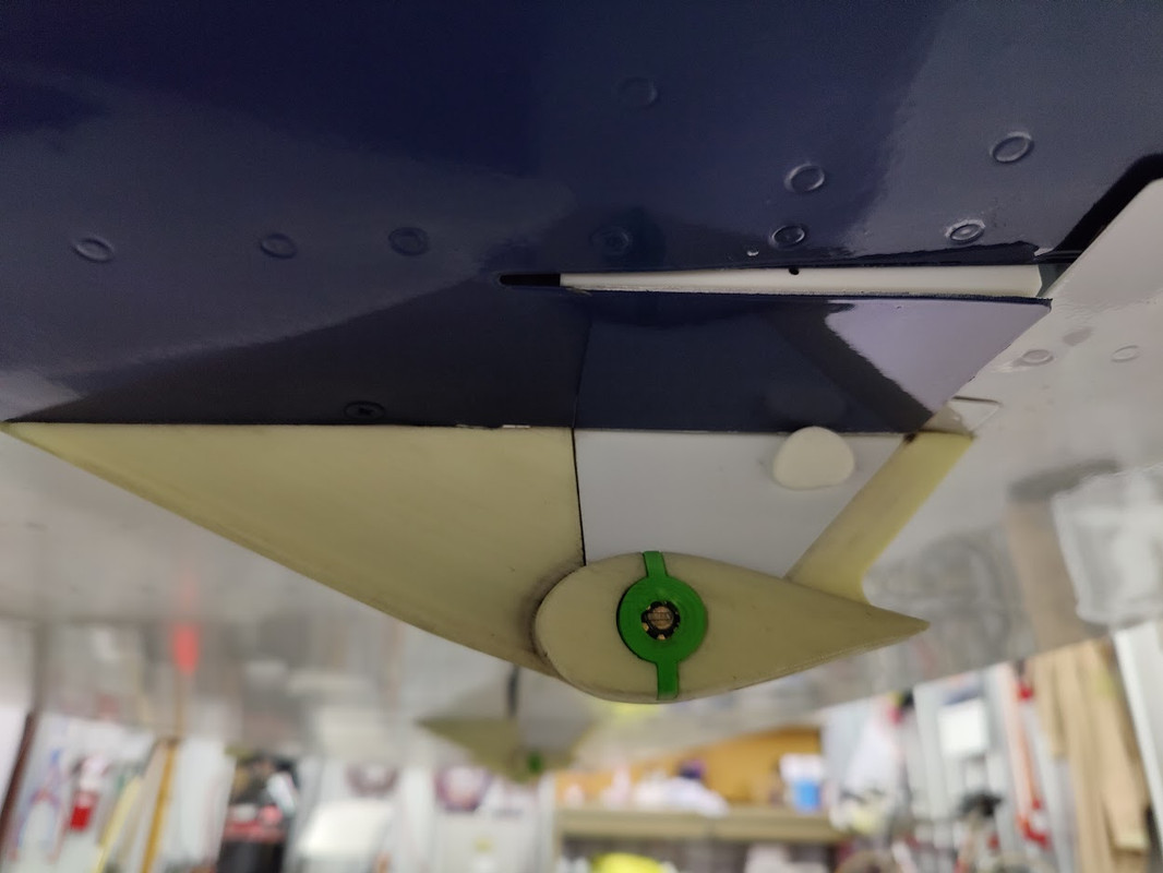
flap cover lifter and closeout angle seem to be working. best I can do for an ugly situation.
Phoenix - 1901
https://youtu.be/cFElidiwxYU
Phoenix - 1901
https://youtu.be/cFElidiwxYU
RV9A, Superior O-320, WW 200RV prop, Slick mags, CHT 330F, EGT 1300F, B&C, 1400+ hours
Freedom and Democracy are all that really matter.
Ride a bike, unlock the world.
https://www.rvplasticparts.com/
Freedom and Democracy are all that really matter.
Ride a bike, unlock the world.
https://www.rvplasticparts.com/
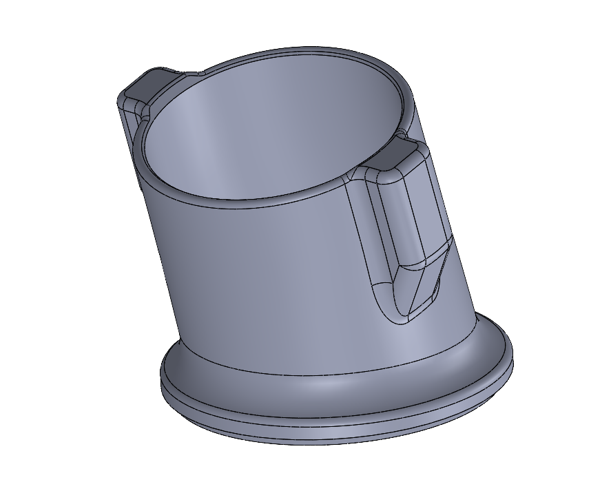
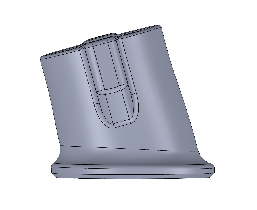
Re: a couple printed widgets
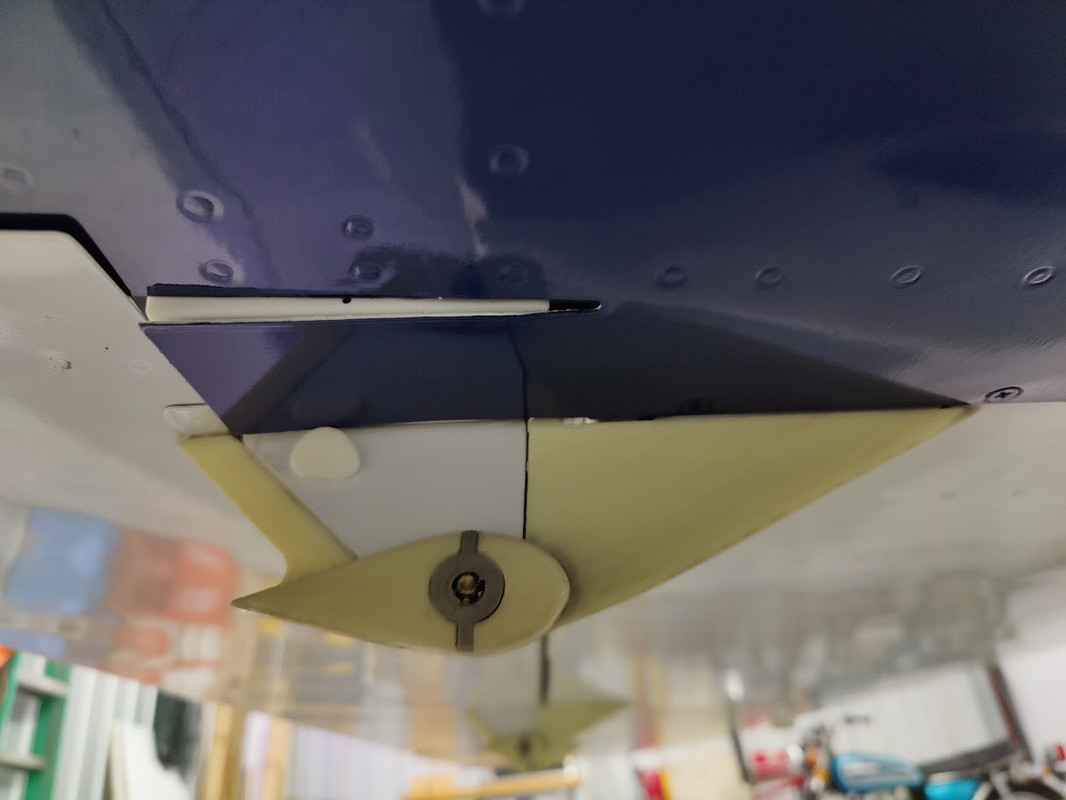
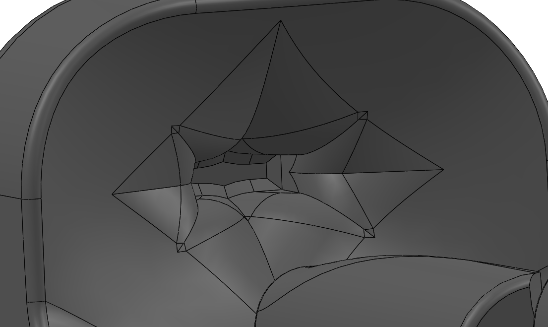
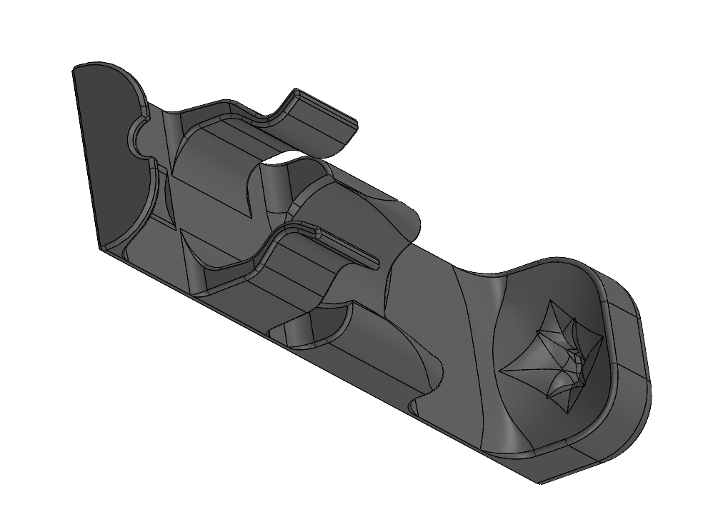
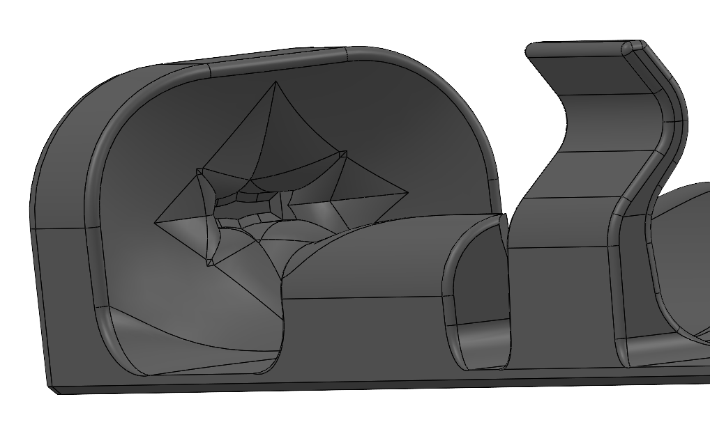
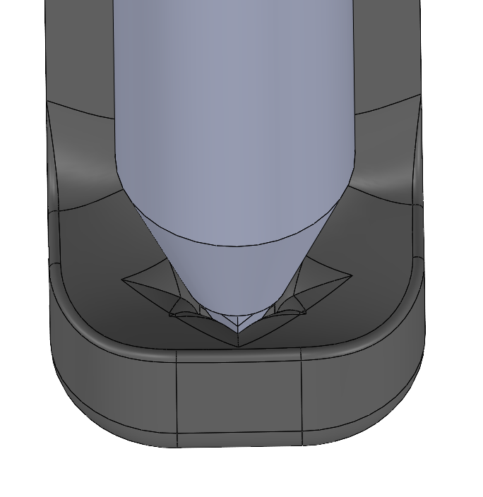
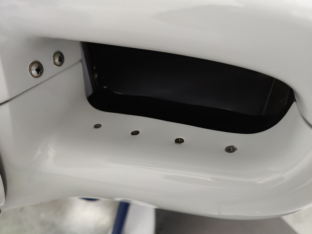
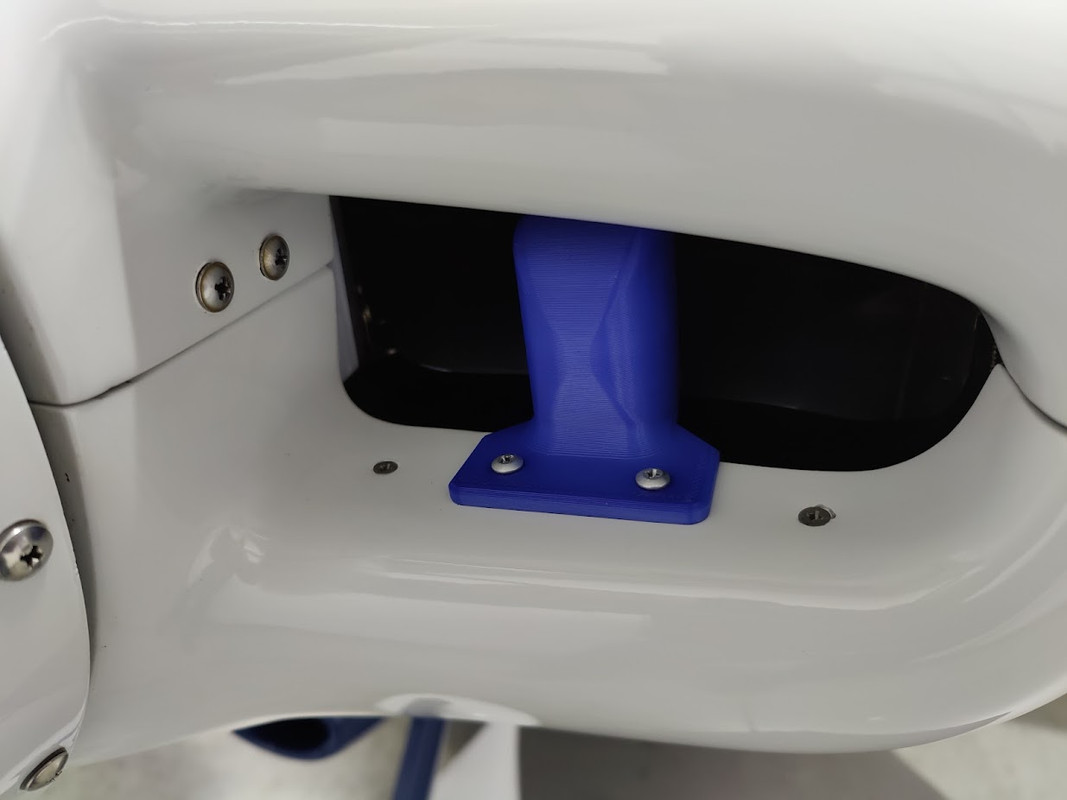
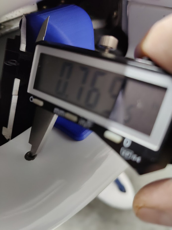
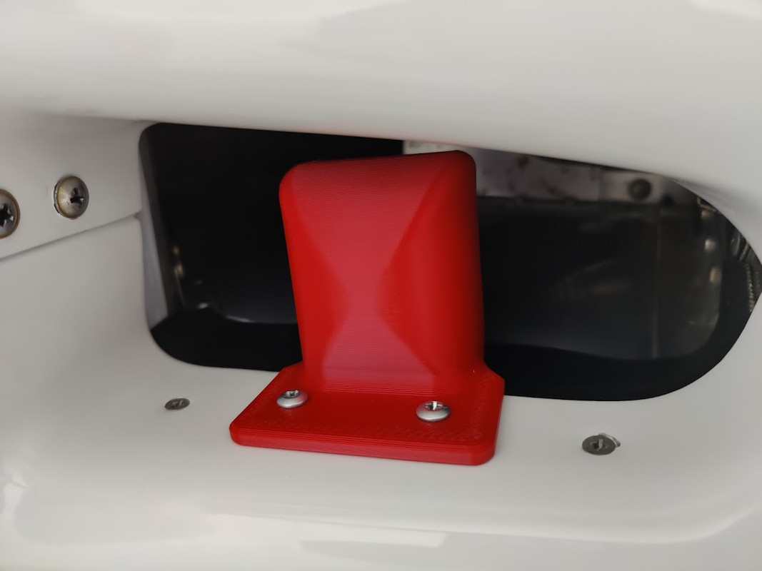
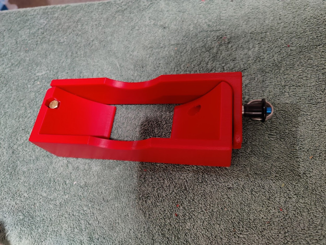
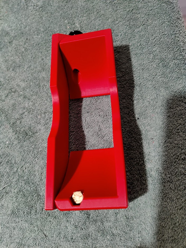
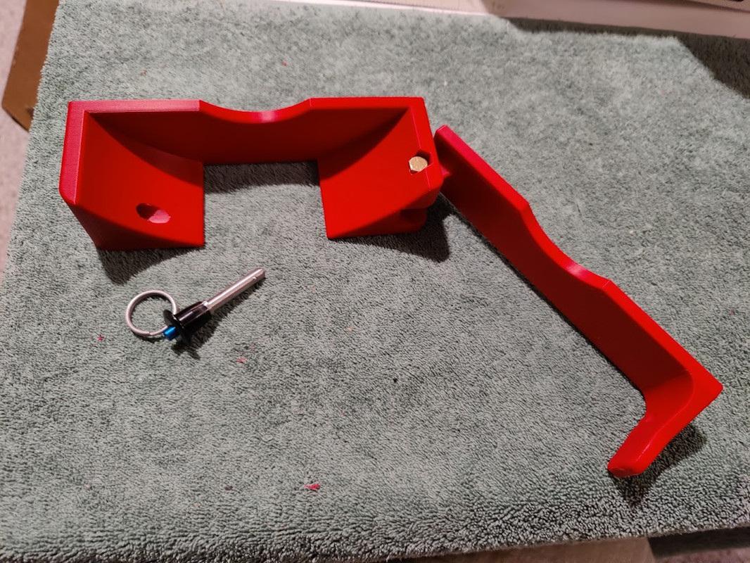
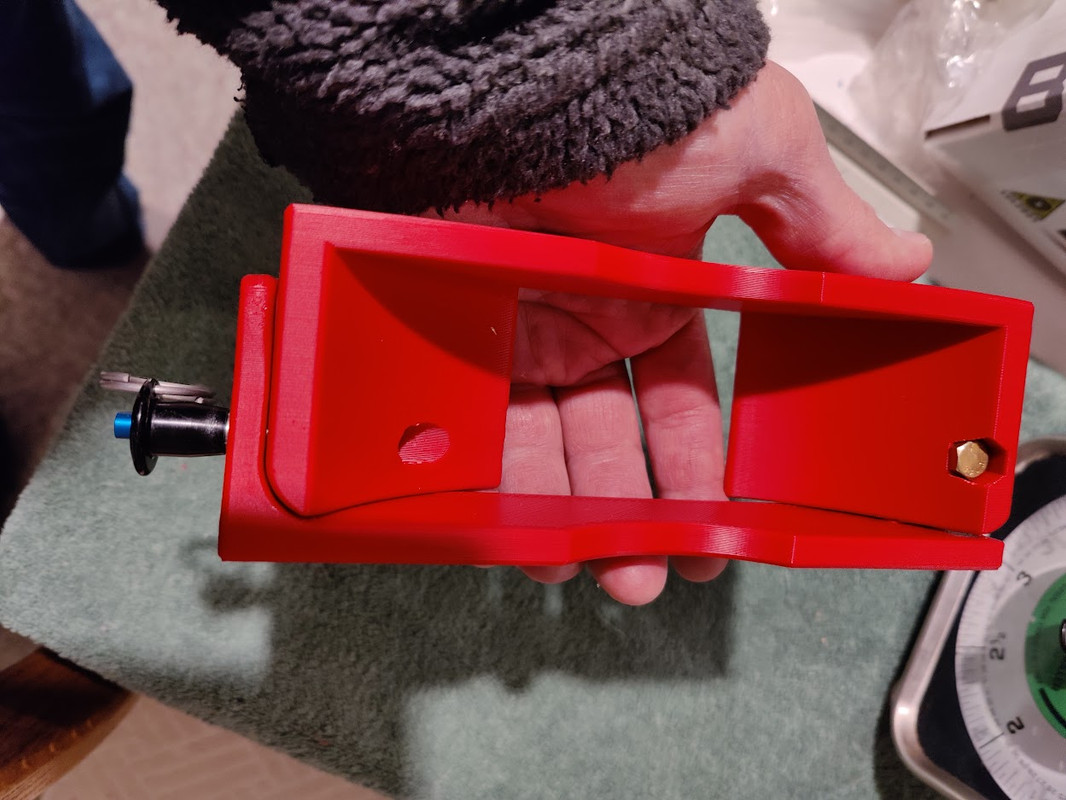
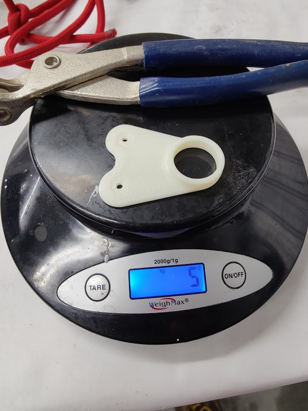
fuel sump mount. updated the lower end to accept both Phillips and standard tips. before it only accepted the Phillips. the geometry is unique.
how do you catch a unique rabbet.... unique up on it.
how do you catch a unique rabbet.... unique up on it.
RV9A, Superior O-320, WW 200RV prop, Slick mags, CHT 330F, EGT 1300F, B&C, 1400+ hours
Freedom and Democracy are all that really matter.
Ride a bike, unlock the world.
https://www.rvplasticparts.com/
Freedom and Democracy are all that really matter.
Ride a bike, unlock the world.
https://www.rvplasticparts.com/
Re: a couple printed widgets
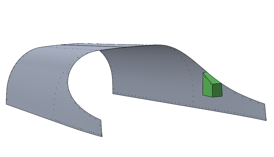
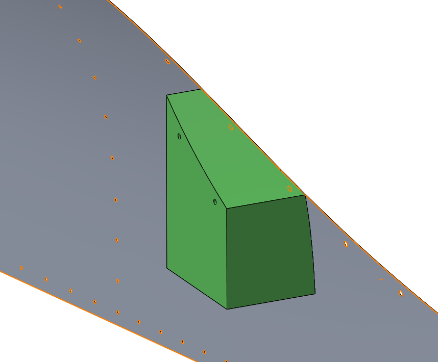
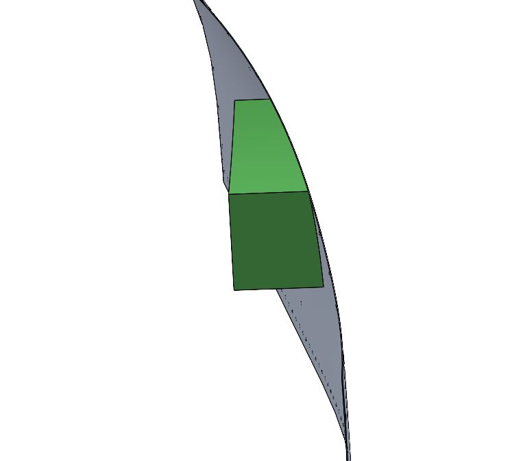
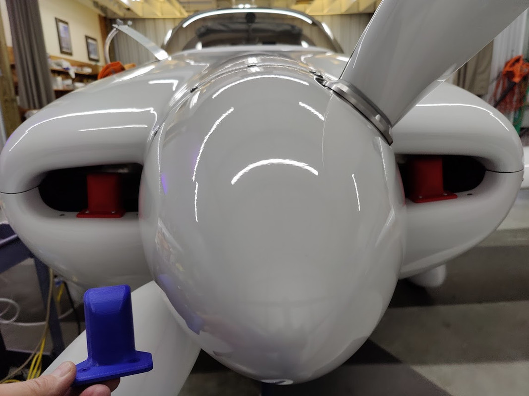
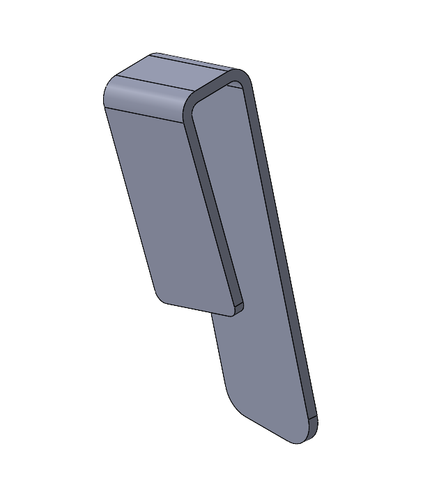
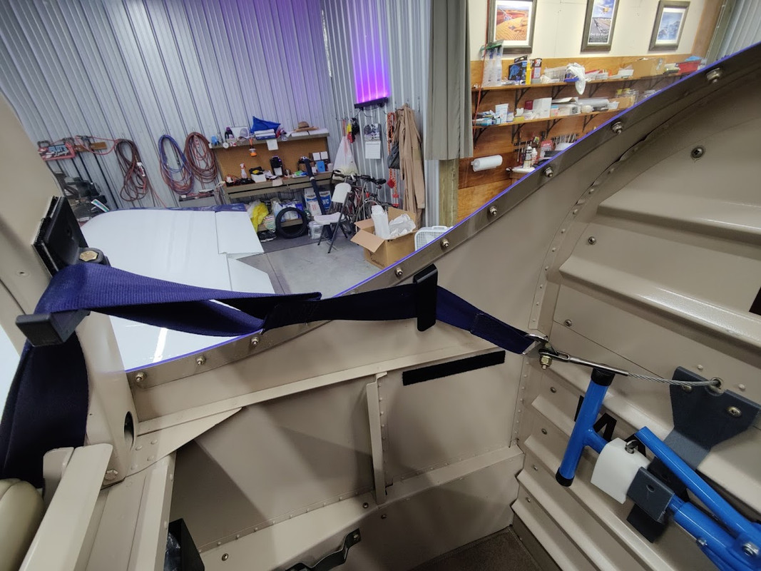
thinking about a secondary seat belt restrainer for loading the bike. need the exact contour from the skin.
***********
I don't know how well this will work, a prototype.


***********
I don't know how well this will work, a prototype.
RV9A, Superior O-320, WW 200RV prop, Slick mags, CHT 330F, EGT 1300F, B&C, 1400+ hours
Freedom and Democracy are all that really matter.
Ride a bike, unlock the world.
https://www.rvplasticparts.com/
Freedom and Democracy are all that really matter.
Ride a bike, unlock the world.
https://www.rvplasticparts.com/
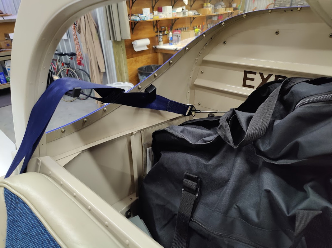
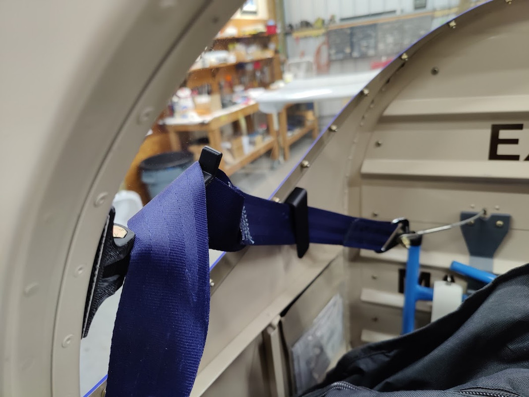
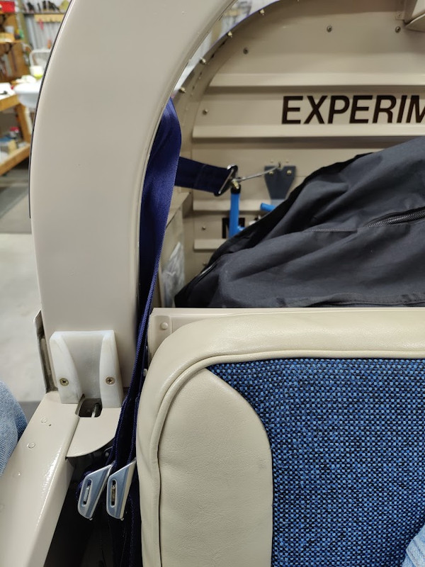
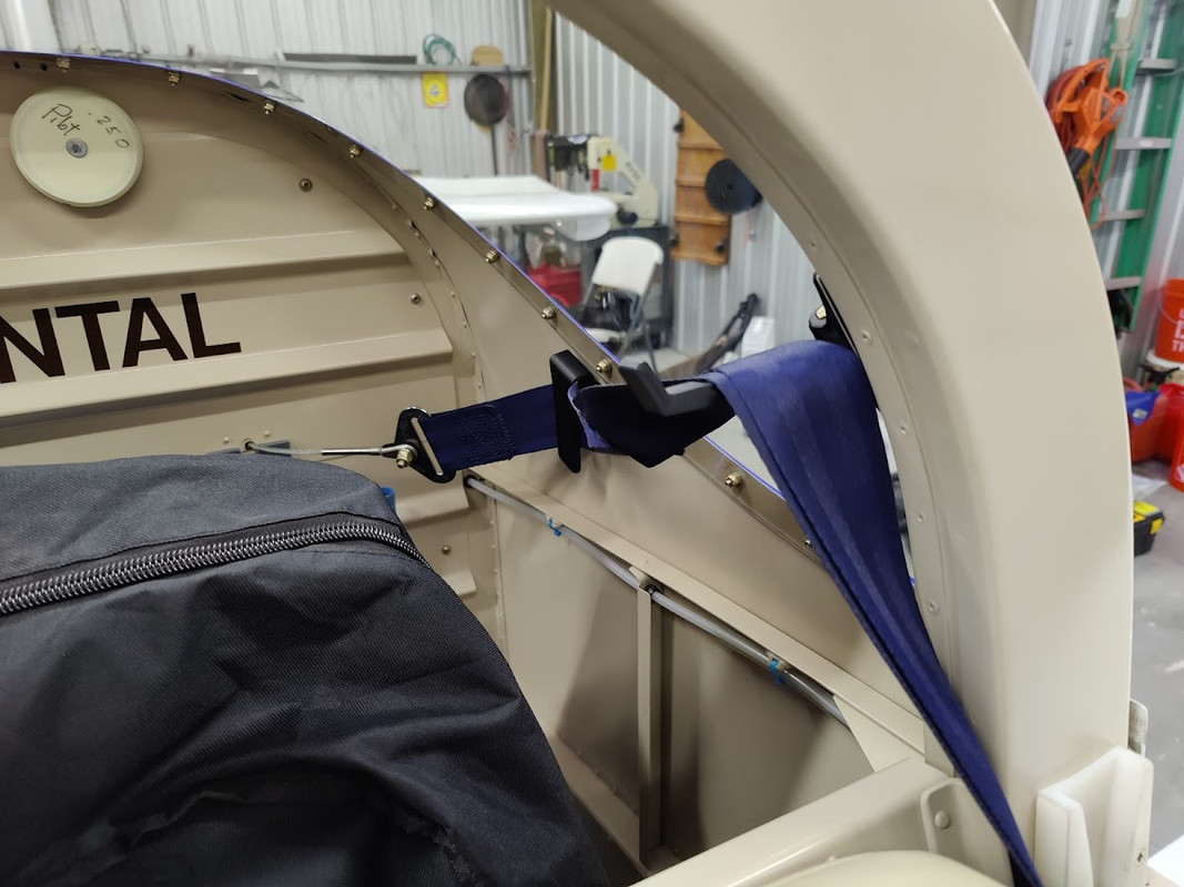
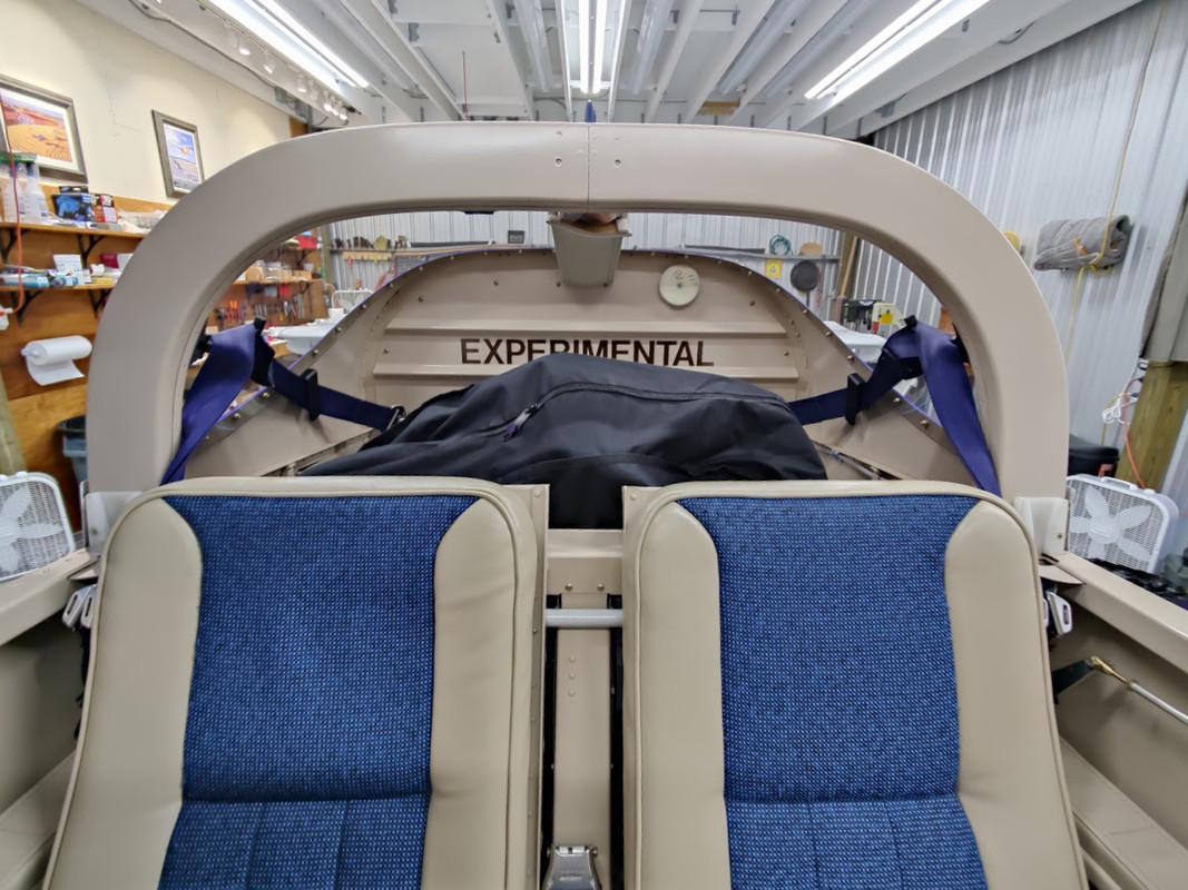
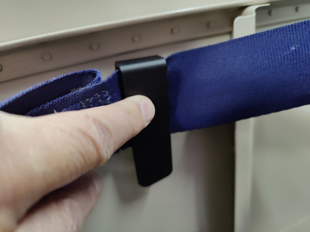
Re: a couple printed widgets
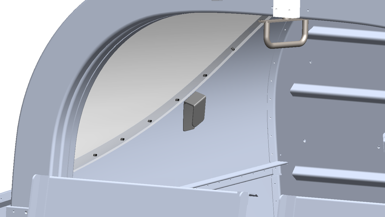
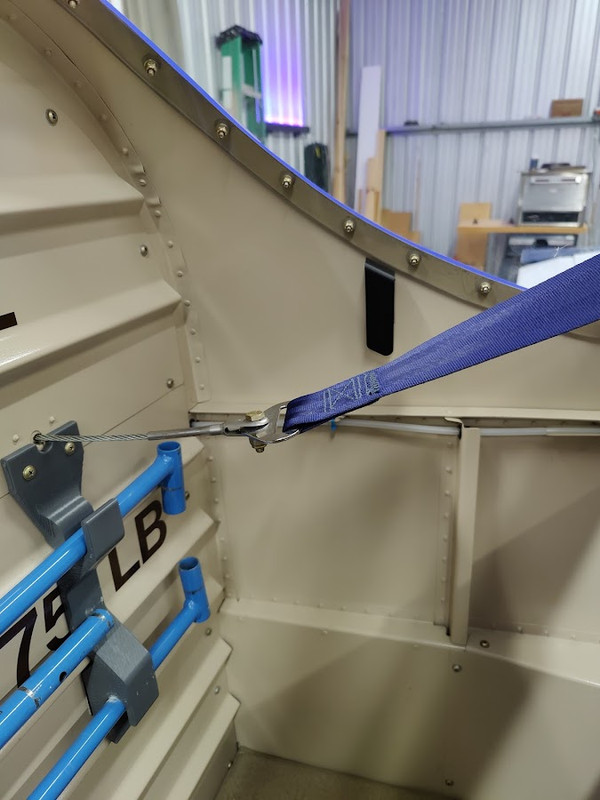
seatbelt restrainer.... good fit. I'll try it for a while. good for holding the belt out of the way for loading. installed between screws 6-7.


RV9A, Superior O-320, WW 200RV prop, Slick mags, CHT 330F, EGT 1300F, B&C, 1400+ hours
Freedom and Democracy are all that really matter.
Ride a bike, unlock the world.
https://www.rvplasticparts.com/
Freedom and Democracy are all that really matter.
Ride a bike, unlock the world.
https://www.rvplasticparts.com/
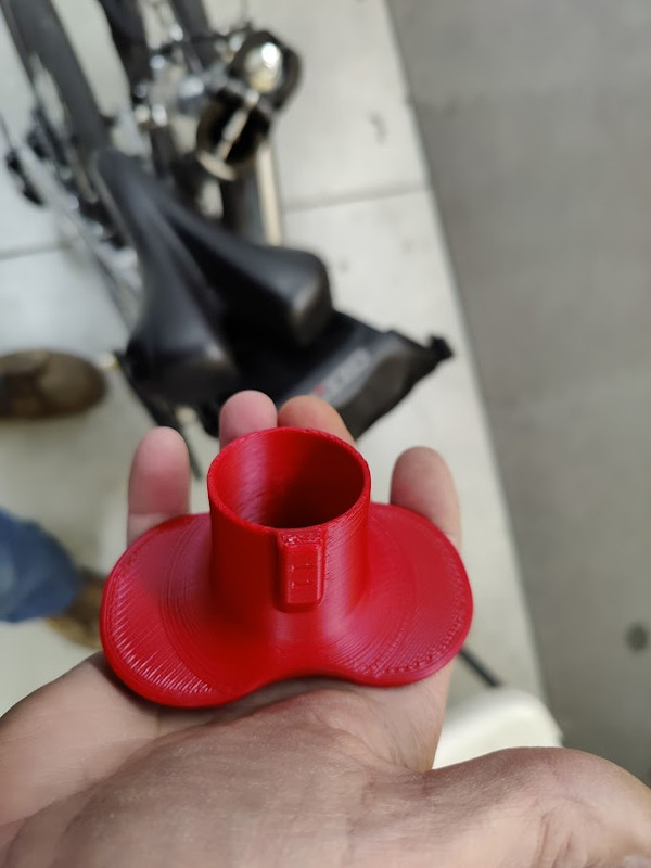
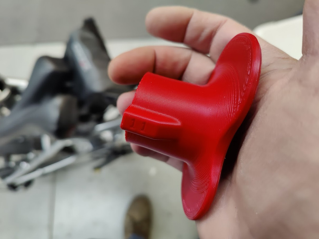
Re: a couple printed widgets
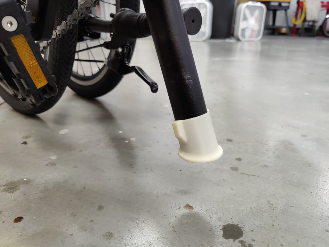
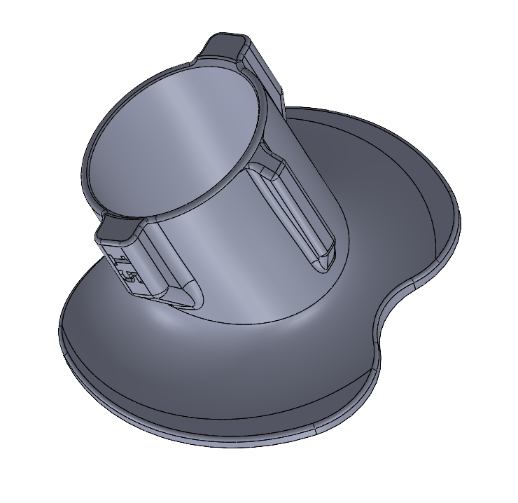
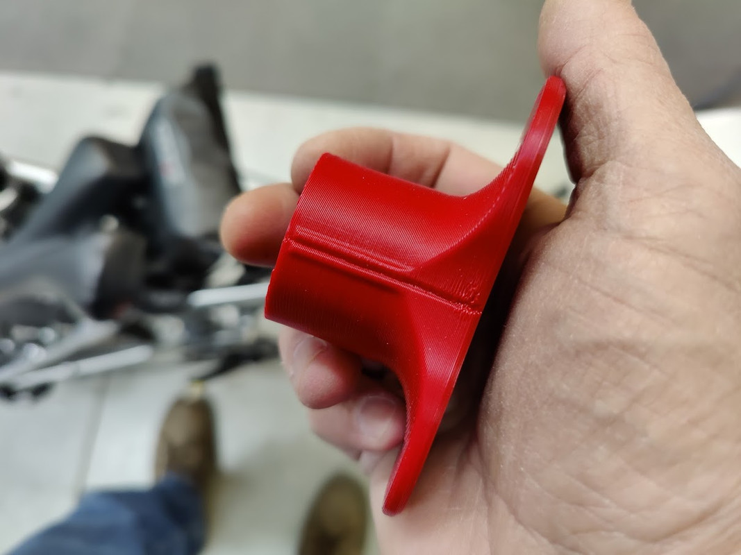
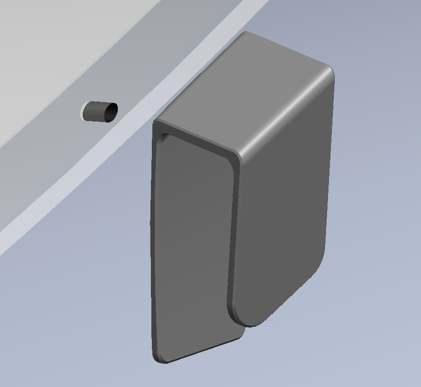
Zizzo seat post protector when stored. the seat post is a hard point when stored. elliptical shape for first 0.5 inch (squeeze) for retention then cylindrical.
Lane 8 feat. Rae Morris - No Fun (Official Music Video) (@Rae Morris)
https://youtu.be/Xpuh2ZSPYZc

Lane 8 feat. Rae Morris - No Fun (Official Music Video) (@Rae Morris)
https://youtu.be/Xpuh2ZSPYZc
RV9A, Superior O-320, WW 200RV prop, Slick mags, CHT 330F, EGT 1300F, B&C, 1400+ hours
Freedom and Democracy are all that really matter.
Ride a bike, unlock the world.
https://www.rvplasticparts.com/
Freedom and Democracy are all that really matter.
Ride a bike, unlock the world.
https://www.rvplasticparts.com/
Re: a couple printed widgets
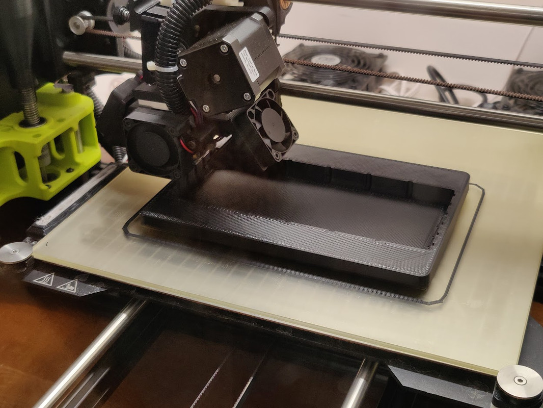
I haven't printed one of these in a while, but I like this part, Odyssey PC680 battery tray, lightweight and functional. I think this one is going to Canada. my first shipment to Iceland was last week.... that was cool. Worldwide!
Marsh - Liberator [Live from Natural Bridge State Park, Kentucky]
https://youtu.be/Q4BQCTGfFIw
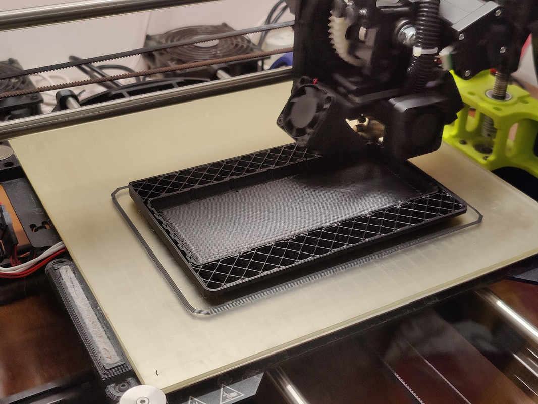
********
almost completed, another layer or two
Marsh - Liberator [Live from Natural Bridge State Park, Kentucky]
https://youtu.be/Q4BQCTGfFIw
********
almost completed, another layer or two
RV9A, Superior O-320, WW 200RV prop, Slick mags, CHT 330F, EGT 1300F, B&C, 1400+ hours
Freedom and Democracy are all that really matter.
Ride a bike, unlock the world.
https://www.rvplasticparts.com/
Freedom and Democracy are all that really matter.
Ride a bike, unlock the world.
https://www.rvplasticparts.com/
Re: a couple printed widgets
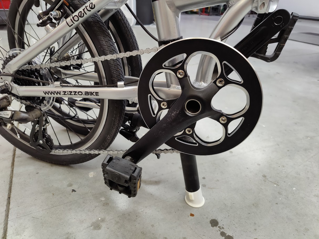
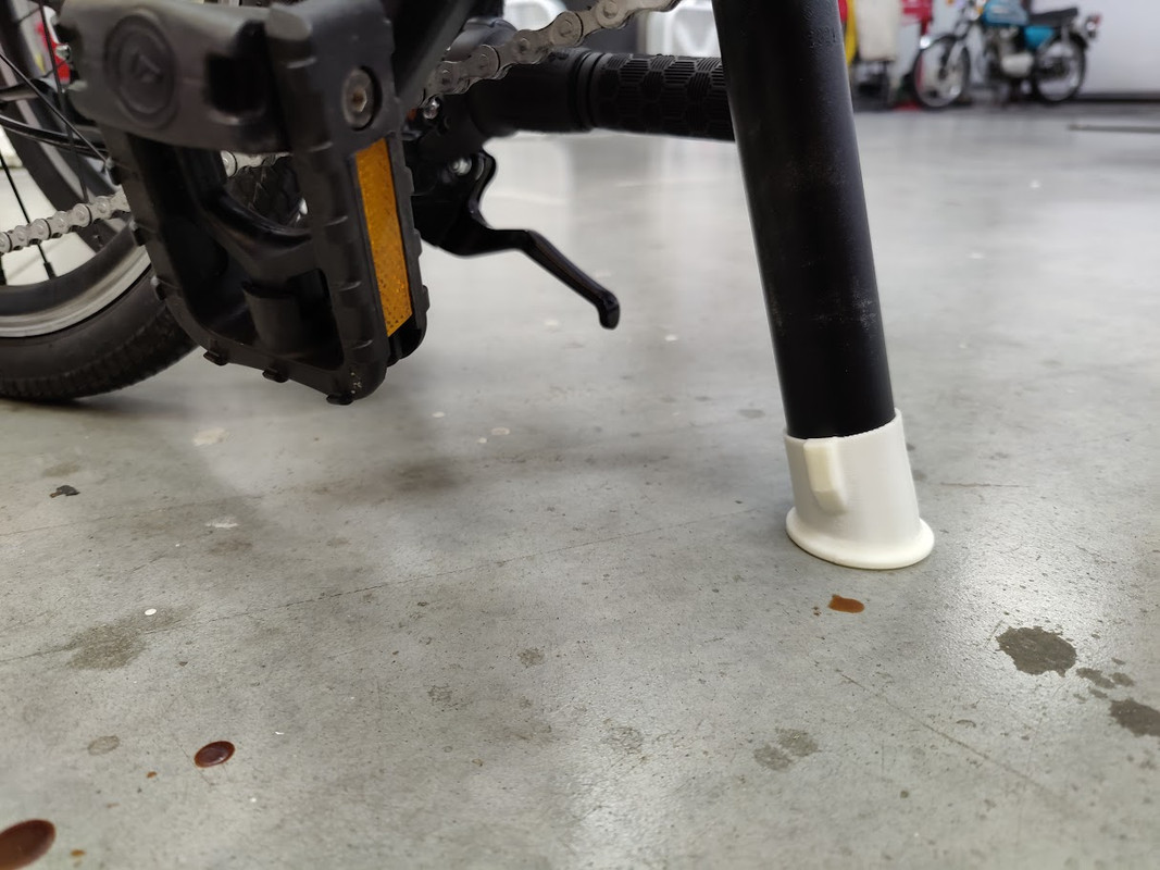
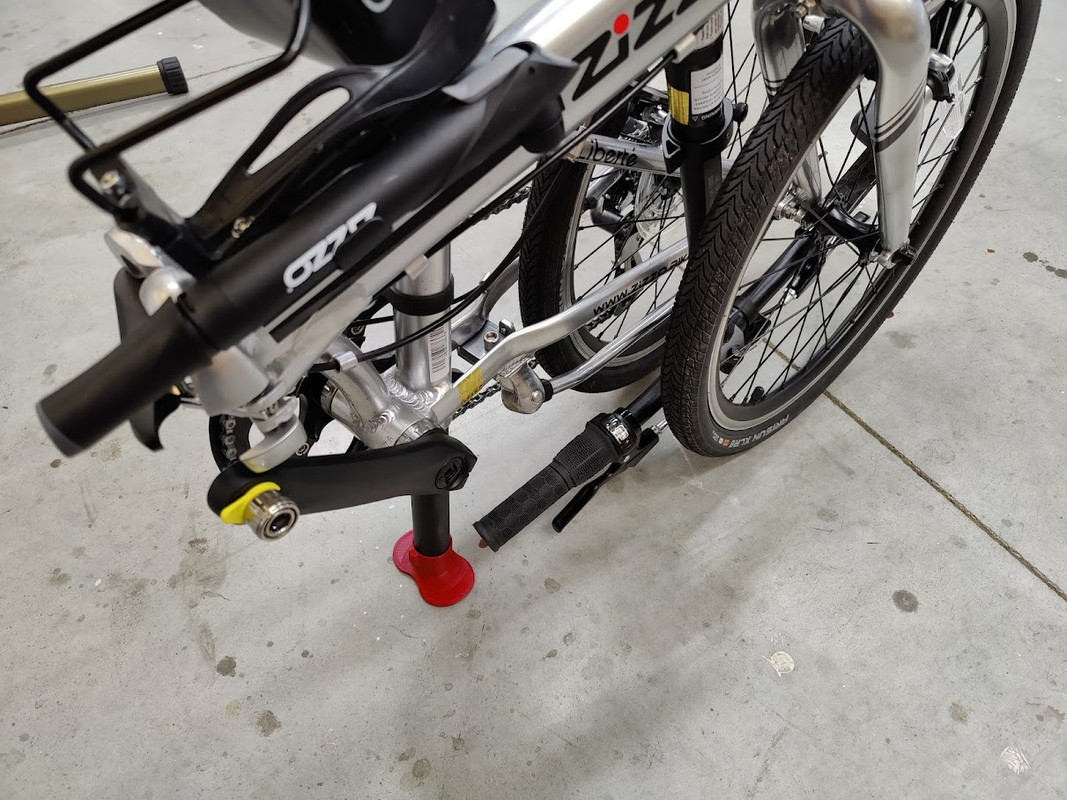
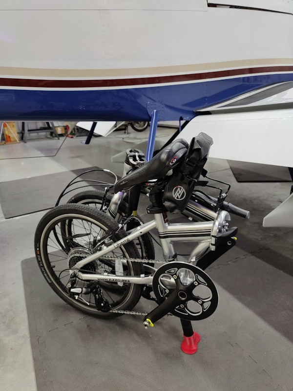
Zizzo seat post protector. I noticed the seat post has a plug to give some protection, but this adds some more. also, the tipping stability is increased. I think I will enlarge the base to add even more tipping stability. the slip fit and retention is good. the angle is good.

*********************
updated design, getting closer to the finished design..... thinking this geometry will self-rotate to the flattest position. need to test.
the sleeve is elliptical for the first half inch (12.7mm) then cylindrical.
*********************
updated design, getting closer to the finished design..... thinking this geometry will self-rotate to the flattest position. need to test.
the sleeve is elliptical for the first half inch (12.7mm) then cylindrical.
Last edited by A2022 on Wed Nov 16, 2022 9:52 am, edited 7 times in total.
RV9A, Superior O-320, WW 200RV prop, Slick mags, CHT 330F, EGT 1300F, B&C, 1400+ hours
Freedom and Democracy are all that really matter.
Ride a bike, unlock the world.
https://www.rvplasticparts.com/
Freedom and Democracy are all that really matter.
Ride a bike, unlock the world.
https://www.rvplasticparts.com/
Re: a couple printed widgets
a TAZ commercial. what's shipping today from RVPlasticParts? fresh plastic. I need a t-shirt that says, "I press buttons and listen to music". I need to get a digital music mixer and have women dancing at the hangar.... behind the airplane.
yep, that's a dray grey Garmin 760 mount, beautiful.
Gratitude (Extended Mix)
Nora En Pure
https://youtu.be/1KI_uvwgsVc
Fill My Heart
Luttrell Official
https://youtu.be/Hc0gwBClYGE
Spada, Korolova - Be Strong
https://youtu.be/-jjzheccCto

yep, that's a dray grey Garmin 760 mount, beautiful.
Gratitude (Extended Mix)
Nora En Pure
https://youtu.be/1KI_uvwgsVc
Fill My Heart
Luttrell Official
https://youtu.be/Hc0gwBClYGE
Spada, Korolova - Be Strong
https://youtu.be/-jjzheccCto
RV9A, Superior O-320, WW 200RV prop, Slick mags, CHT 330F, EGT 1300F, B&C, 1400+ hours
Freedom and Democracy are all that really matter.
Ride a bike, unlock the world.
https://www.rvplasticparts.com/
Freedom and Democracy are all that really matter.
Ride a bike, unlock the world.
https://www.rvplasticparts.com/
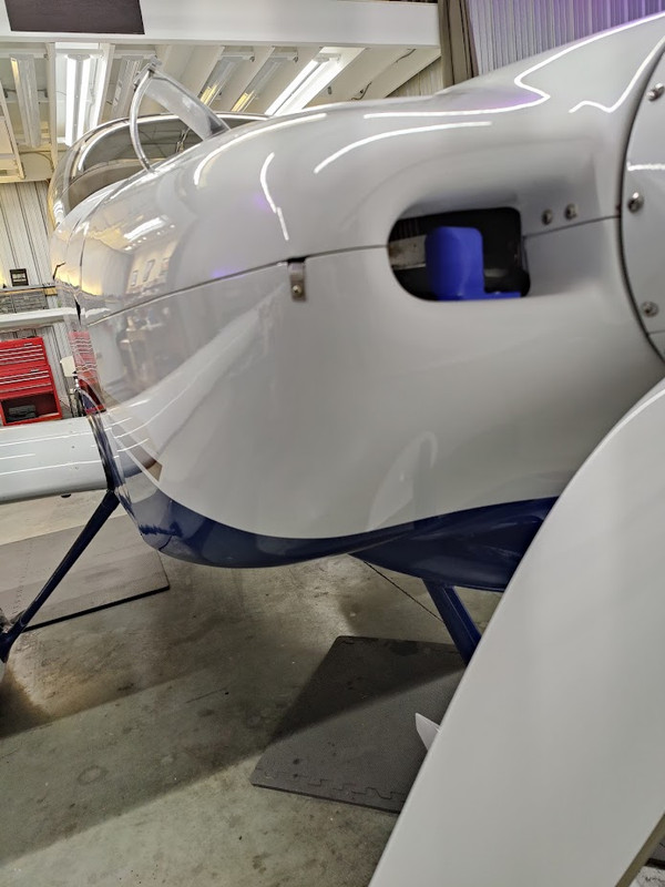
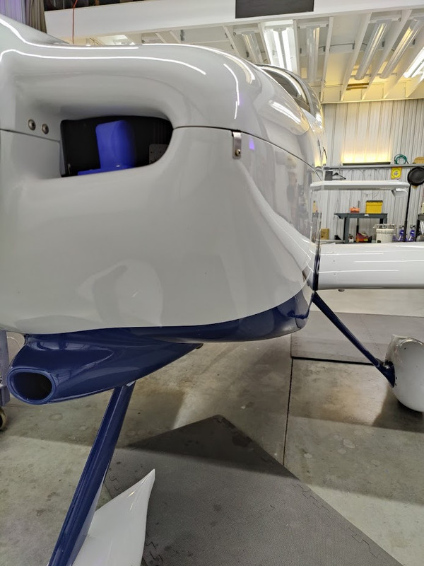
Re: a couple printed widgets
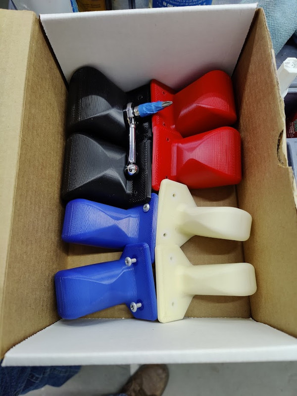
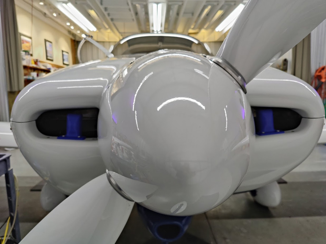
cowl inlet air dams for Winter. the low is going to be -10C here in a couple days so I installed my air dams. my engine seems to do better if I keep the temperature up in the Wintertime. I was consistently having lower compression on a couple cylinders after Winter, but after using the air dams they returned to normal. that's all the evidence I have. going on my 3rd year for these (maybe 4th, I can't remember since I lost my stream on Van's Airforce). 5-minute install and the cowl hasn't suffered any damage from the air dams. 1.5-inch or 2.0-inch wide air dams work well for me (blue or red). 2.5-inch (black) for extreme cold, -30C, but some would say -30C is warm. CHTs remain balanced when the air dam is mounted in the middle of the inlet. these are printed hollow, like a balloon, to keep the air dam natural frequency response high so the blade passing frequency does not interact.
Nora En Pure – Forsaken Dream
https://youtu.be/00DLX6GxiC4


Nora En Pure – Forsaken Dream
https://youtu.be/00DLX6GxiC4
RV9A, Superior O-320, WW 200RV prop, Slick mags, CHT 330F, EGT 1300F, B&C, 1400+ hours
Freedom and Democracy are all that really matter.
Ride a bike, unlock the world.
https://www.rvplasticparts.com/
Freedom and Democracy are all that really matter.
Ride a bike, unlock the world.
https://www.rvplasticparts.com/
Re: a couple printed widgets
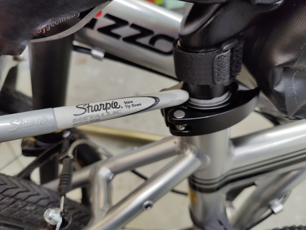
Zizzo seat post sleeve support, to make the bike stabile when folded. slip on grip. done. feels good in the hand. silver metallic sharpie to mark the perfect seat post storage line, when the seat post bag is installed.
it's really nice to walk into a hangar and have a clean airplane. since bug season is basically over in Ohio, I've been taking some time to remove all bugs.... even the wheel pants.
Transmission (ABGT472)
https://youtu.be/fZQNvHg0UPQ


it's really nice to walk into a hangar and have a clean airplane. since bug season is basically over in Ohio, I've been taking some time to remove all bugs.... even the wheel pants.
Transmission (ABGT472)
https://youtu.be/fZQNvHg0UPQ
RV9A, Superior O-320, WW 200RV prop, Slick mags, CHT 330F, EGT 1300F, B&C, 1400+ hours
Freedom and Democracy are all that really matter.
Ride a bike, unlock the world.
https://www.rvplasticparts.com/
Freedom and Democracy are all that really matter.
Ride a bike, unlock the world.
https://www.rvplasticparts.com/
Re: a couple printed widgets
getting ready for a bike ride on Thursday but the low is predicted to be -6C and 3C for the high, so colder. I swapped my 1.5-inch cowl air dams for 2.0-inch. the clock turned 7:04 when I began and just turned 7:08 when I finished, so 4 minutes to swap at a relaxed pace and a torque check. CHT's remained balanced when the inlet blockage is in the middle of the opening. the Zizzo Liberte folding bike is working well.

RV9A, Superior O-320, WW 200RV prop, Slick mags, CHT 330F, EGT 1300F, B&C, 1400+ hours
Freedom and Democracy are all that really matter.
Ride a bike, unlock the world.
https://www.rvplasticparts.com/
Freedom and Democracy are all that really matter.
Ride a bike, unlock the world.
https://www.rvplasticparts.com/
Re: a couple printed widgets
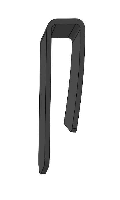
seat belt side restrainer. needs to be longer and is now narrower. I'll test it for a while.
old
******************
new
old
******************
new
RV9A, Superior O-320, WW 200RV prop, Slick mags, CHT 330F, EGT 1300F, B&C, 1400+ hours
Freedom and Democracy are all that really matter.
Ride a bike, unlock the world.
https://www.rvplasticparts.com/
Freedom and Democracy are all that really matter.
Ride a bike, unlock the world.
https://www.rvplasticparts.com/
Re: a couple printed widgets
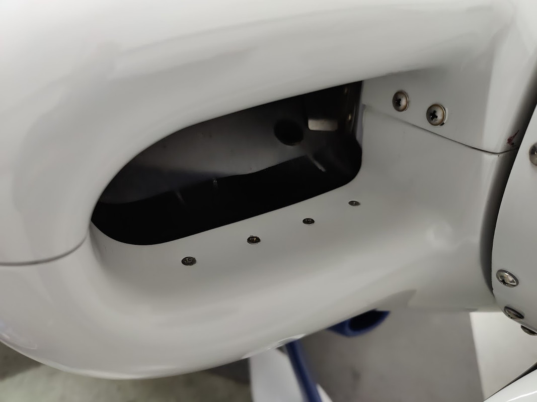
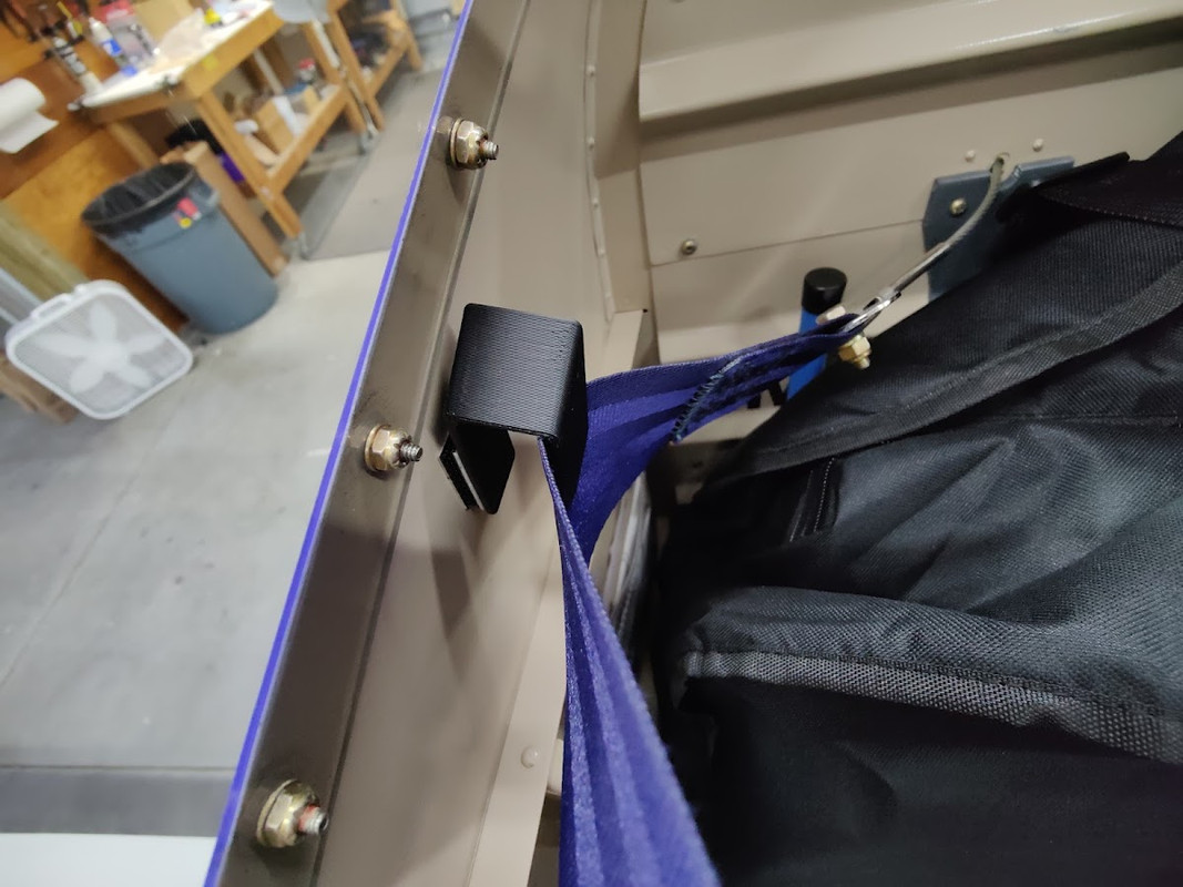
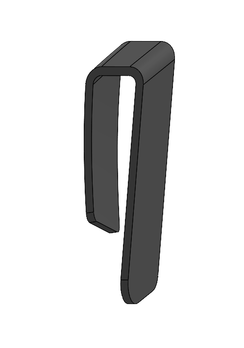
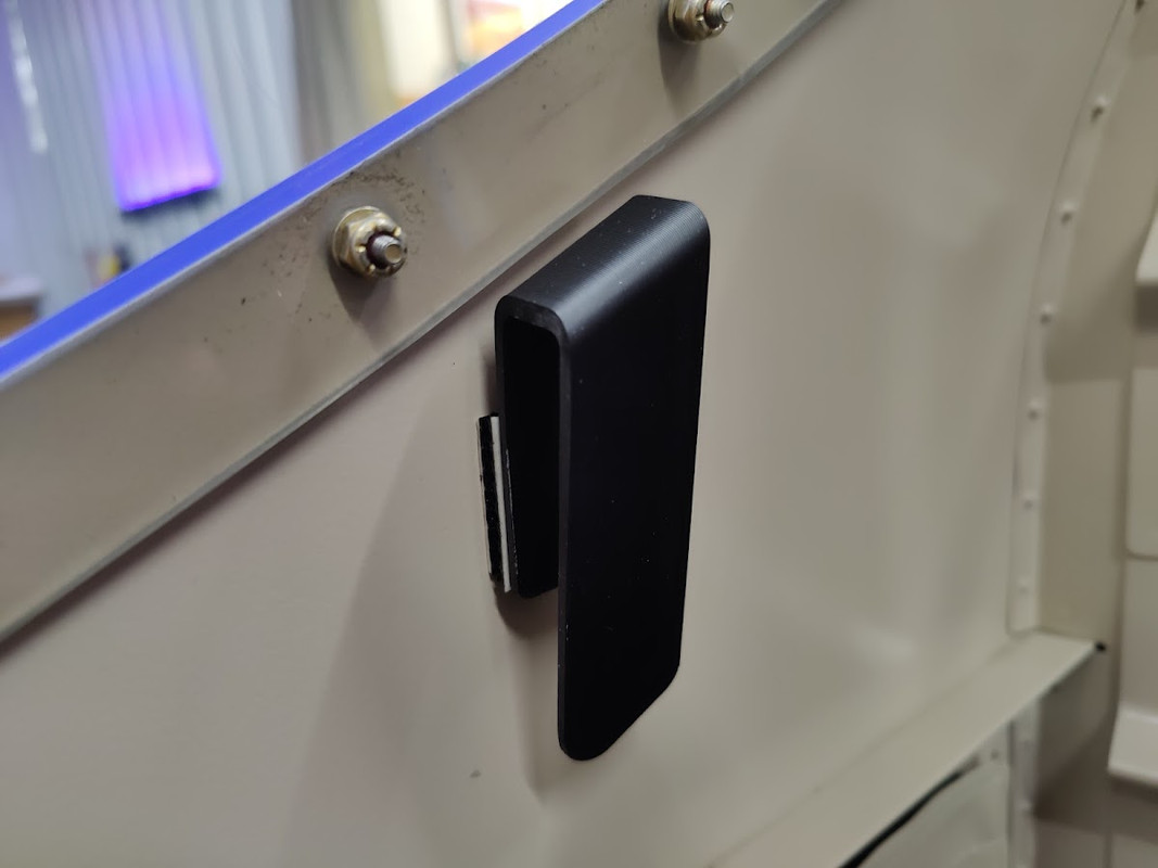
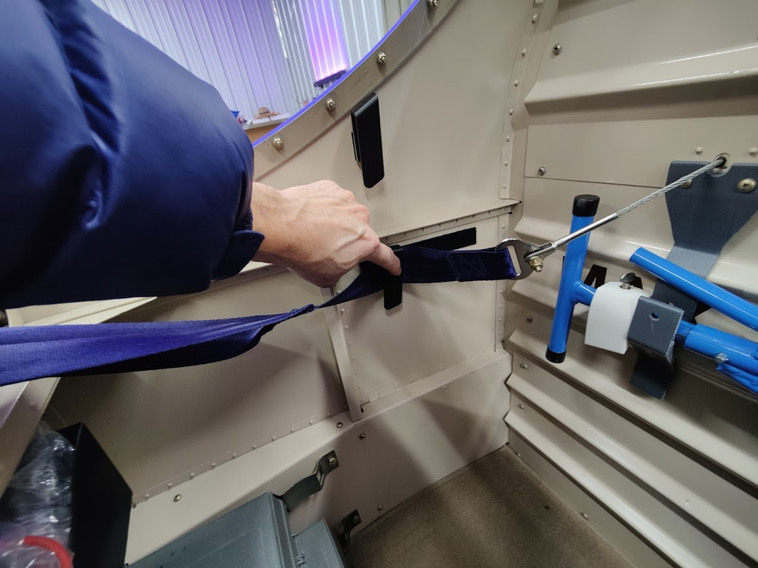
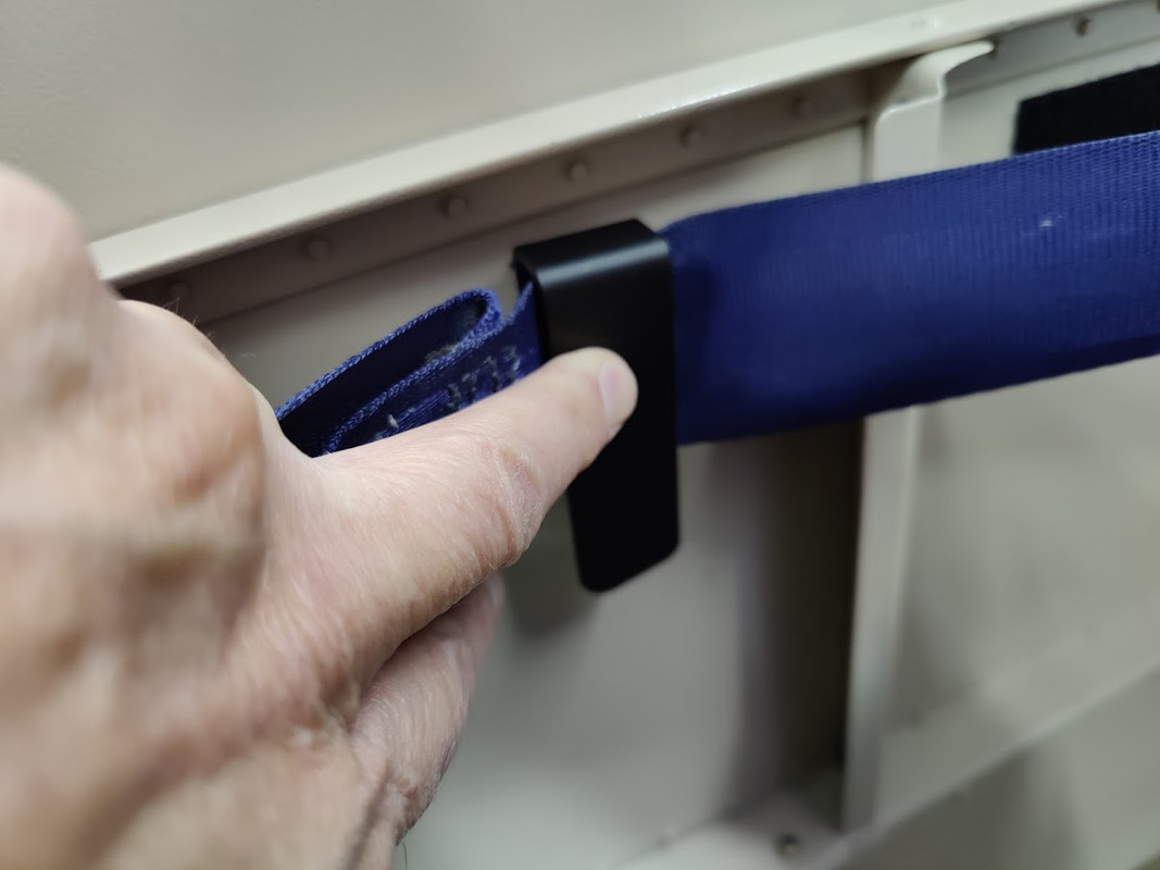
seat belt side restrainer V2. better than V1. I'll test it for a while. these only work with the seat belt hooks. opens the spacing for loading bikes. these restrainers match the skin contour between the 6-7 aft canopy screws, counted from the forward side.
once, when loading a bike, the seat beat became caught, and the weight of the bike pulled a seat belt hook (the one attached to the roll bar) off its dual lock Velcro mount. so, I snapped it back on and all is good. I think 3M Dual Lock Velcro is the way to go for these hooks. the Dual Lock on mine are original and a couple years old and no signs of any adverse condition and always subjected to the hanging loads of the belts when not in use.
Marsh, Lailonie (Extended Mix)
https://youtu.be/MSwOYIIPh-U
RV9A, Superior O-320, WW 200RV prop, Slick mags, CHT 330F, EGT 1300F, B&C, 1400+ hours
Freedom and Democracy are all that really matter.
Ride a bike, unlock the world.
https://www.rvplasticparts.com/
Freedom and Democracy are all that really matter.
Ride a bike, unlock the world.
https://www.rvplasticparts.com/
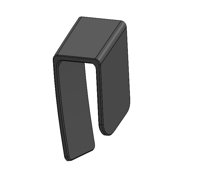
Re: a couple printed widgets
another seat belt restrainer for the baggage area. a simple part that may be useful to restrain the belt to the side if you do not have roll bar mounted seat belt hooks. a prototype....
a couple options for placement but it does not get the belt up as high and out of the way as when using the roll bar mounted hooks.


a couple options for placement but it does not get the belt up as high and out of the way as when using the roll bar mounted hooks.
RV9A, Superior O-320, WW 200RV prop, Slick mags, CHT 330F, EGT 1300F, B&C, 1400+ hours
Freedom and Democracy are all that really matter.
Ride a bike, unlock the world.
https://www.rvplasticparts.com/
Freedom and Democracy are all that really matter.
Ride a bike, unlock the world.
https://www.rvplasticparts.com/
Re: a couple printed widgets
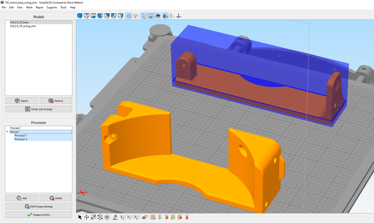
taking a look at the new Simplify3D V5. new options and features. Simplify3D is a local Cincinnati company that makes 3D printing slicer software for machine g-code. I have found their software to be very reliable. this model is a tailwheel chock for someone, the print is finishing.
it will be nice to get some real-world usage information on this widget, as it has only been tested locally at my home airport. 6 ounces (170 grams), lightweight and feels good in the hand, no sharp edges. the goal is to secure the aircraft with one chock in light to medium ground winds. can be installed with only one hand if necessary.

**********
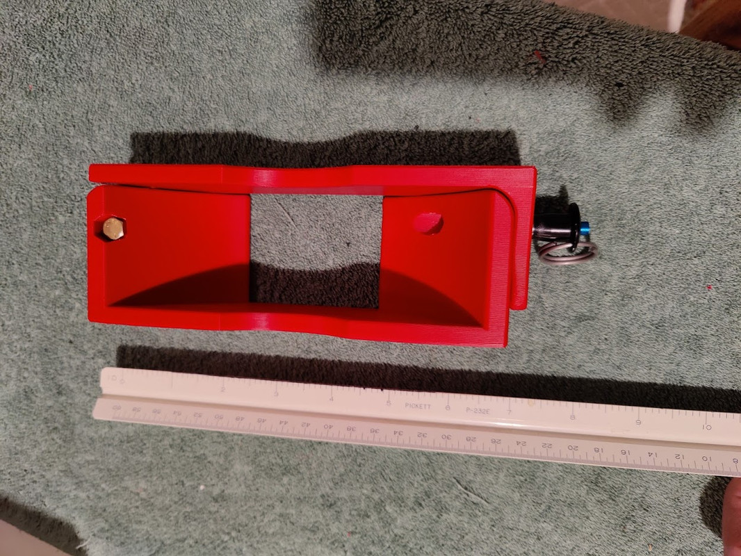


it will be nice to get some real-world usage information on this widget, as it has only been tested locally at my home airport. 6 ounces (170 grams), lightweight and feels good in the hand, no sharp edges. the goal is to secure the aircraft with one chock in light to medium ground winds. can be installed with only one hand if necessary.
**********
RV9A, Superior O-320, WW 200RV prop, Slick mags, CHT 330F, EGT 1300F, B&C, 1400+ hours
Freedom and Democracy are all that really matter.
Ride a bike, unlock the world.
https://www.rvplasticparts.com/
Freedom and Democracy are all that really matter.
Ride a bike, unlock the world.
https://www.rvplasticparts.com/
Re: a couple printed widgets
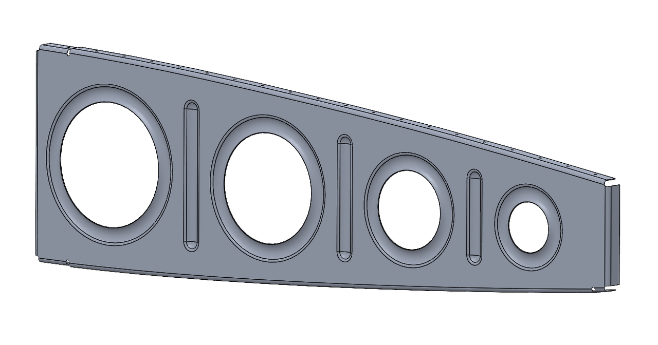
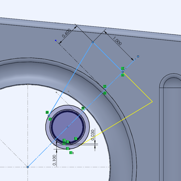
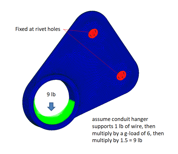
a conduit hanger could be a handy part. a simple part to design and make. follow along.

*********************
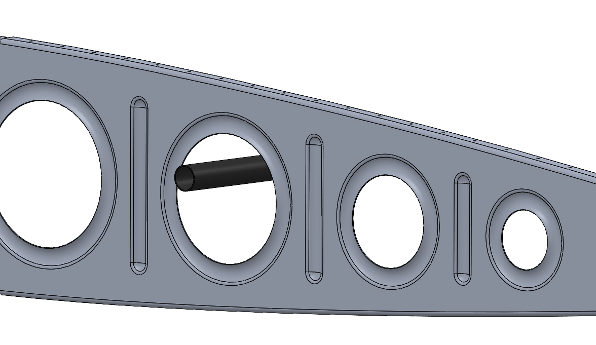
since we don't know the final location of the part yet, I'll add a circle and extrude it to make the conduit. the conduit location will be adjusted later.

***********************
OK, that was 10 minutes of work, need to take a coffee break.
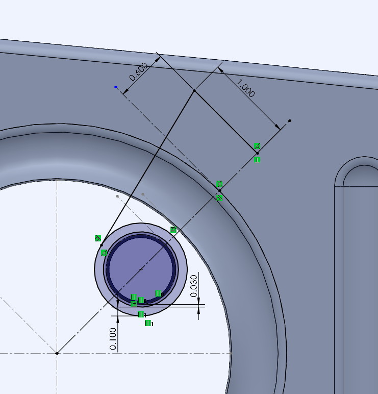
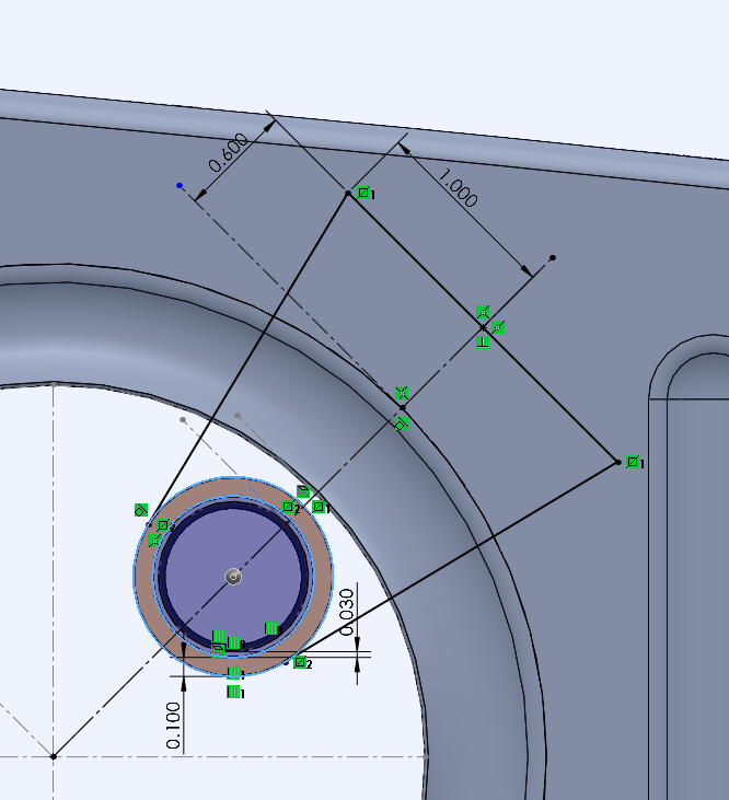
offset the outer conduit circle .03 for clearance. then offset that circle .10 inch to make the outer ring of the hanger. draw half of the rivet mounting surface and then mirror it and extrude it .10 inch. all of these dimensions will be fine-tuned later, we are working to get the basic shape now.


OK, that was another 10 minutes, time to take a break and listen to some music.
***********************
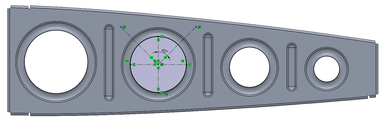
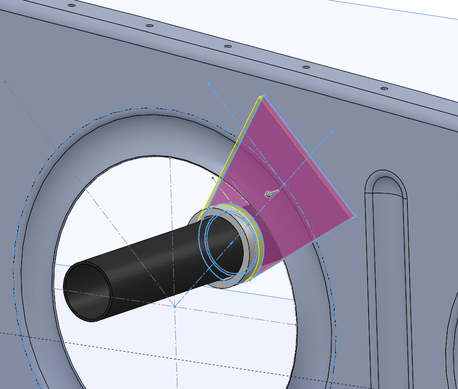
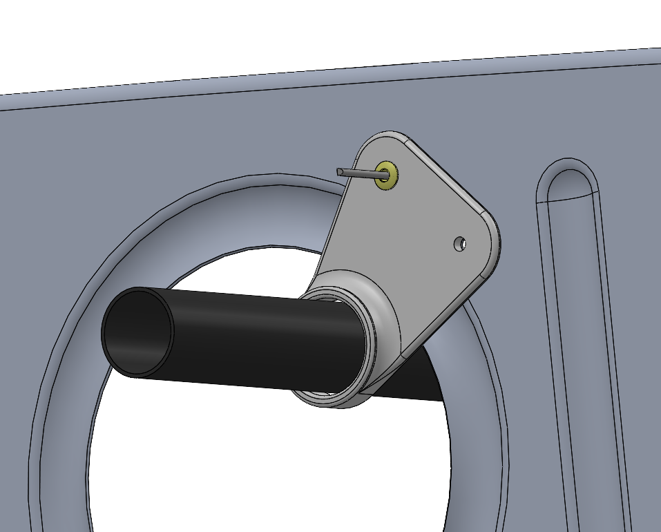
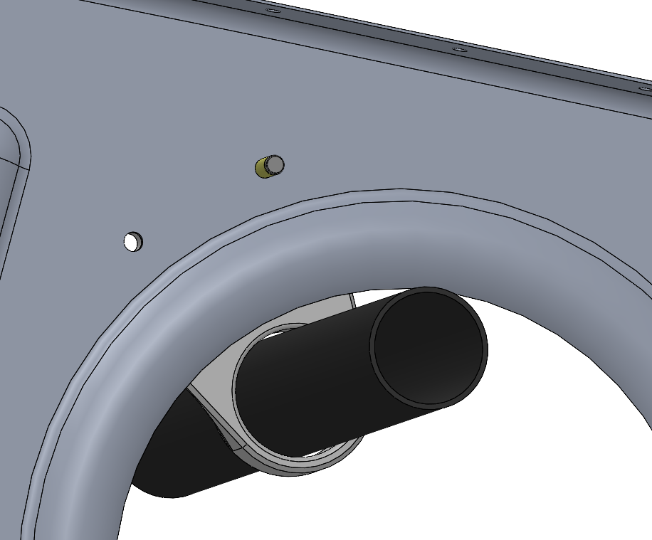
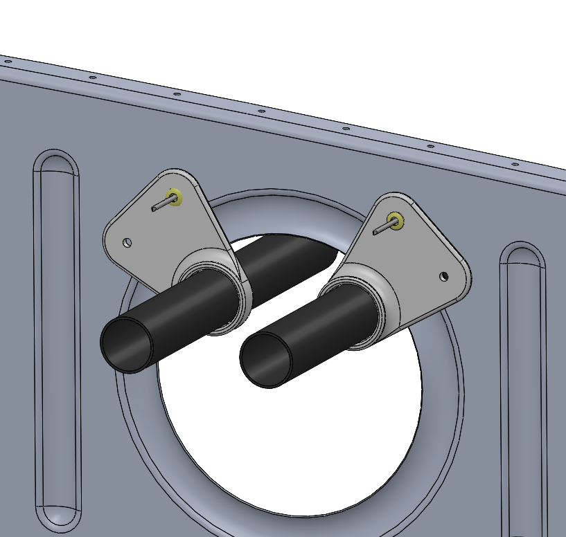
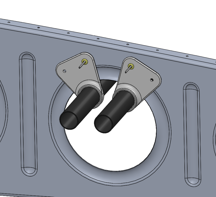
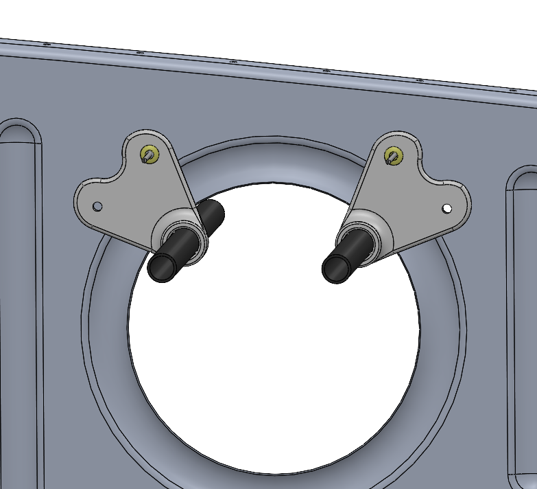
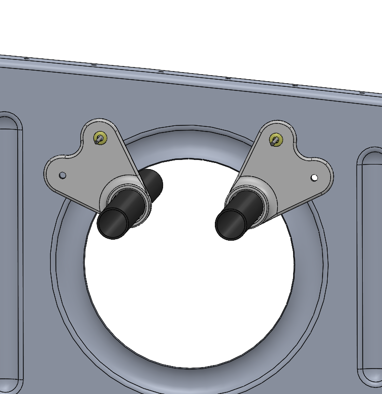
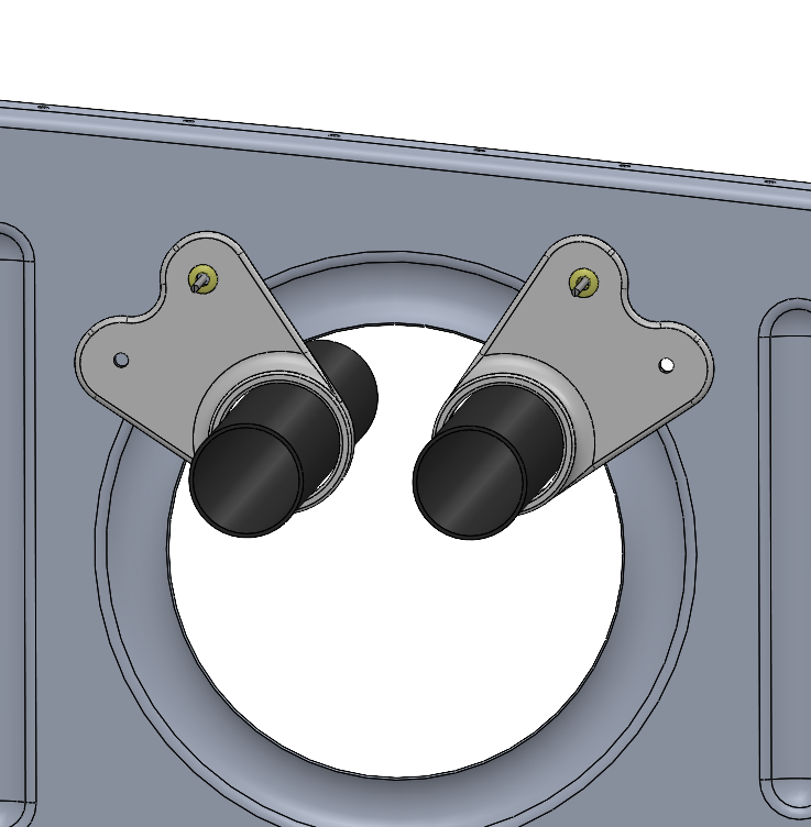
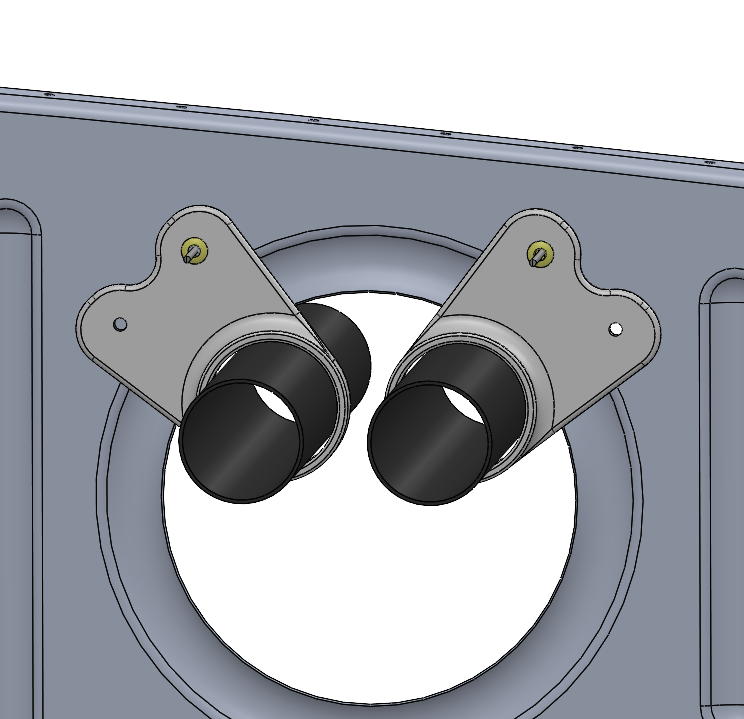
add some holes, fillets and a chamfer. snug the conduit closer to the edge of the lightening hole. decrease the clearance to the conduit to be .04 inch diametrical. show the arrangement with two conduit tubes at 45 degrees (baseline), 30 degrees and 60 degrees.
OK, that was another 15 minutes. time to print one for a test fit and determine if I can take some weight out.
so, about 1 hr working time to do one of these from scratch at a very relaxed pace. it's just play for me now.


*************************
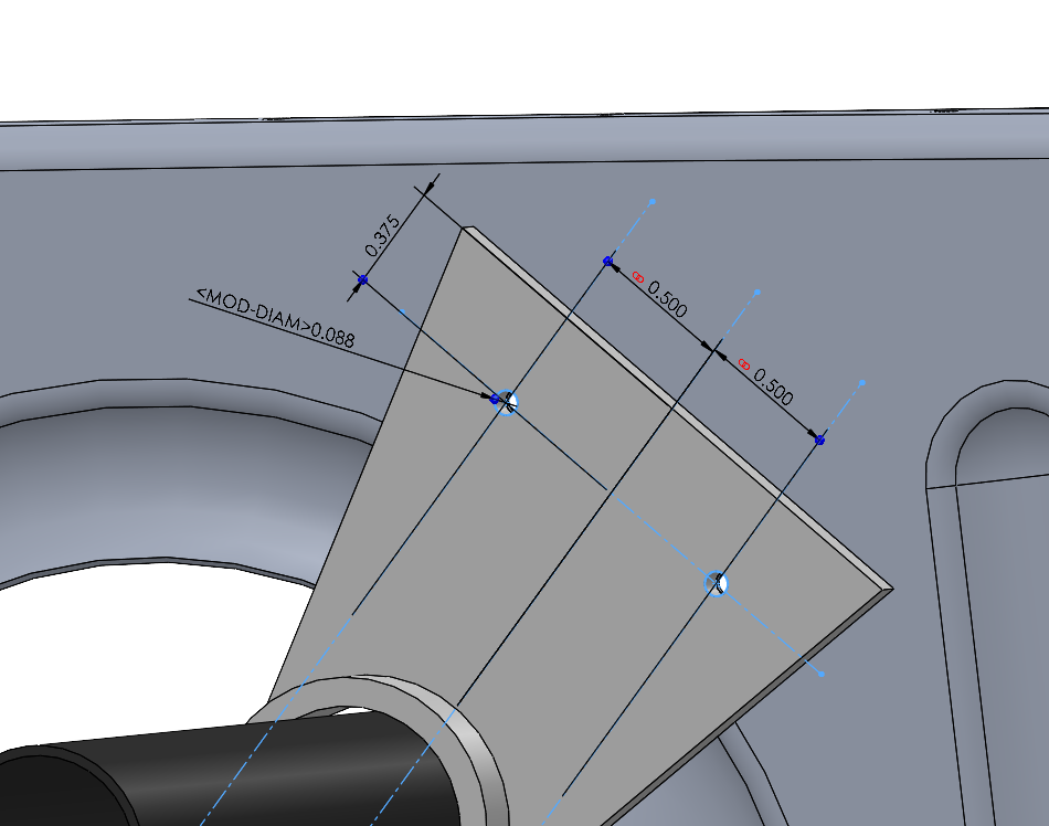
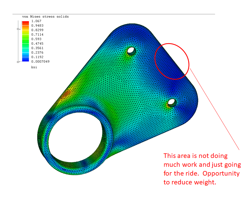
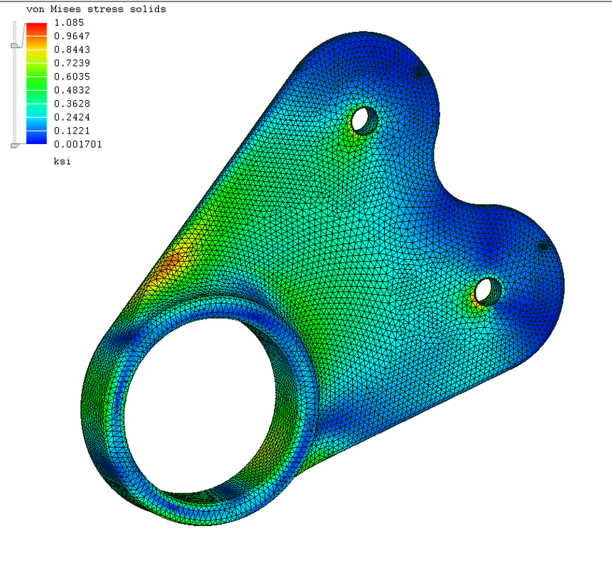
assume conduit hanger supports 1 lb of wire, then multiply by a g-load of 6, then multiply by 1.5 = 9 lb. the most outboard area is not doing much work and just going for the ride. opportunity to reduce weight, but we already knew that the material between bolt holes generally doesn't do much work, right? the next time you see a scalloped flange, you will know why.

************************
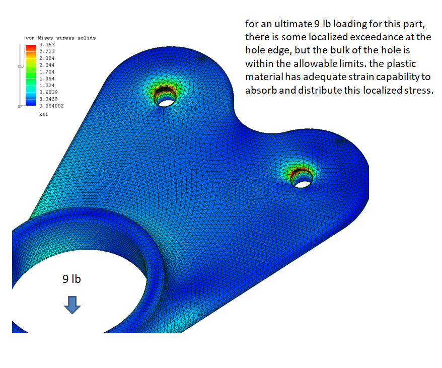
taking a closer look at the rivet holes to simulate compression only at rivet hole wall that is closer to the real condition. for an ultimate 9 lb loading for this part, there is some localized exceedance at the hole edge, but the bulk of the hole is within the allowable limits. the plastic material has adequate strain capability to absorb and distribute this localized stress.

*********************
since we don't know the final location of the part yet, I'll add a circle and extrude it to make the conduit. the conduit location will be adjusted later.
***********************
OK, that was 10 minutes of work, need to take a coffee break.
offset the outer conduit circle .03 for clearance. then offset that circle .10 inch to make the outer ring of the hanger. draw half of the rivet mounting surface and then mirror it and extrude it .10 inch. all of these dimensions will be fine-tuned later, we are working to get the basic shape now.
OK, that was another 10 minutes, time to take a break and listen to some music.
***********************
add some holes, fillets and a chamfer. snug the conduit closer to the edge of the lightening hole. decrease the clearance to the conduit to be .04 inch diametrical. show the arrangement with two conduit tubes at 45 degrees (baseline), 30 degrees and 60 degrees.
OK, that was another 15 minutes. time to print one for a test fit and determine if I can take some weight out.
so, about 1 hr working time to do one of these from scratch at a very relaxed pace. it's just play for me now.
*************************
assume conduit hanger supports 1 lb of wire, then multiply by a g-load of 6, then multiply by 1.5 = 9 lb. the most outboard area is not doing much work and just going for the ride. opportunity to reduce weight, but we already knew that the material between bolt holes generally doesn't do much work, right? the next time you see a scalloped flange, you will know why.
************************
taking a closer look at the rivet holes to simulate compression only at rivet hole wall that is closer to the real condition. for an ultimate 9 lb loading for this part, there is some localized exceedance at the hole edge, but the bulk of the hole is within the allowable limits. the plastic material has adequate strain capability to absorb and distribute this localized stress.
RV9A, Superior O-320, WW 200RV prop, Slick mags, CHT 330F, EGT 1300F, B&C, 1400+ hours
Freedom and Democracy are all that really matter.
Ride a bike, unlock the world.
https://www.rvplasticparts.com/
Freedom and Democracy are all that really matter.
Ride a bike, unlock the world.
https://www.rvplasticparts.com/
Re: a couple printed widgets
Cowl inlet air dams. I switched from 1.5 inch to 2-inch width air dams about a month ago and I have been noticing a faint whistle since then when I am letting down to an airport at max speed. I am wondering if the 2-inch air dams are causing it, so I thought I would try test it by adding some vortex generator the sides of the 2-inch air dams. I am not sure how well I can print these but probably good enough for a test.
Eli & Fur - Skyway
https://youtu.be/UTqfhu7TwFA
2-inch air dams currently installed.

******************
with vortex generators and yes, I realize the vortex will be fighting each other.


Eli & Fur - Skyway
https://youtu.be/UTqfhu7TwFA
2-inch air dams currently installed.
******************
with vortex generators and yes, I realize the vortex will be fighting each other.
RV9A, Superior O-320, WW 200RV prop, Slick mags, CHT 330F, EGT 1300F, B&C, 1400+ hours
Freedom and Democracy are all that really matter.
Ride a bike, unlock the world.
https://www.rvplasticparts.com/
Freedom and Democracy are all that really matter.
Ride a bike, unlock the world.
https://www.rvplasticparts.com/
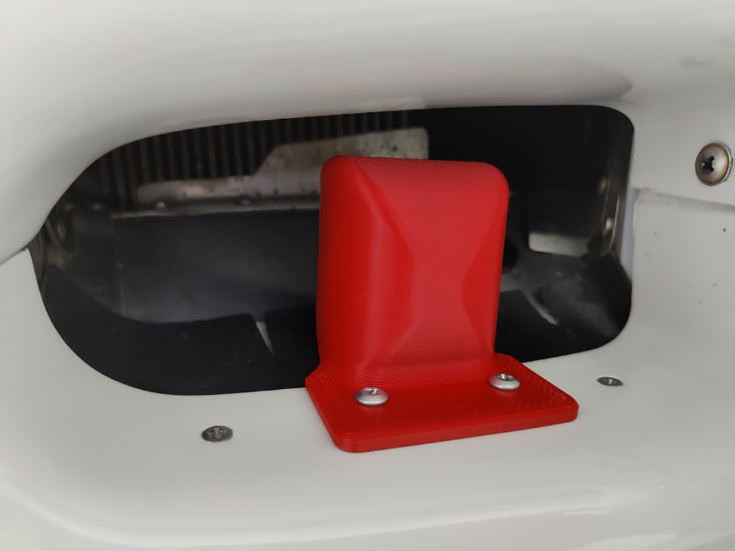
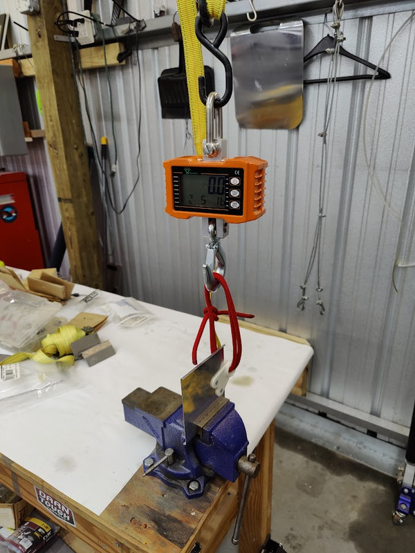
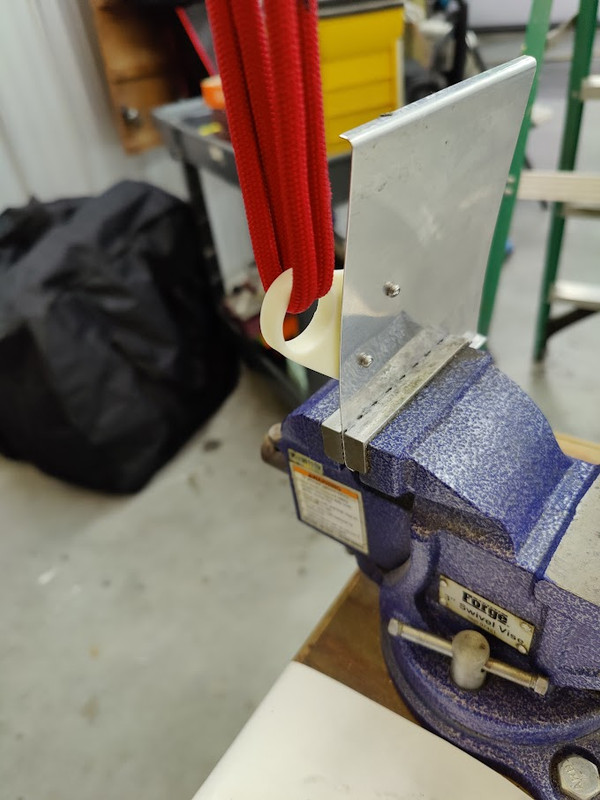
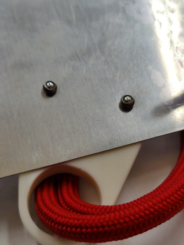
Re: a couple printed widgets
pull testing the conduit holder. a pull test to failure doesn't mean the part can take the pull test loading 10,000 times. the stress analysis concludes that it can withstand a 1 lb wire weight load (1 g-load), 6 lb cycling limit (6g-loading) load and 9 lb ultimate. this test is simply a sanity check. this part made it to 77 lbs with no visual adverse effects. it could have gone higher, but the test setup was marginal and risky for the operator. the part was attached to .025 2024-T3 sheet using LP4-3 rivets. part weight = 5 grams.


Last edited by A2022 on Tue Jan 03, 2023 12:33 pm, edited 2 times in total.
RV9A, Superior O-320, WW 200RV prop, Slick mags, CHT 330F, EGT 1300F, B&C, 1400+ hours
Freedom and Democracy are all that really matter.
Ride a bike, unlock the world.
https://www.rvplasticparts.com/
Freedom and Democracy are all that really matter.
Ride a bike, unlock the world.
https://www.rvplasticparts.com/
Re: a couple printed widgets
conduit hanger. the nice thing about these models is the sizes are easily adjustable. the conduit outer diameter is adjusted to change the shape of the hanger. you will also need to adjust the diametrical clearance to be about 5 percent of the conduit outer diameter (I need to verify this is the best number but should be close). you can make the clearance a function of the outer diameter in the modeling software. then change the conduit outer diameter (one number) and everything adjusts. people use all different sizes and stuff for conduit. here are some examples to show variation: 10mm, 15mm, 20mm, 25mm, 30mm. I don't know why anyone would use anything bigger than about 20mm. that is about it for this example. thx for following along. back to the music for me.
Enamour feat. Meliha - Say Hello
https://youtu.be/lLFBTOMRcjI

Enamour feat. Meliha - Say Hello
https://youtu.be/lLFBTOMRcjI
RV9A, Superior O-320, WW 200RV prop, Slick mags, CHT 330F, EGT 1300F, B&C, 1400+ hours
Freedom and Democracy are all that really matter.
Ride a bike, unlock the world.
https://www.rvplasticparts.com/
Freedom and Democracy are all that really matter.
Ride a bike, unlock the world.
https://www.rvplasticparts.com/